|
|
| Home-->F1 Rocket Project-->Engine Page 9 |
|
SITE CONTENTS
Please send your comments and suggestions to: Copyright
© 2008 by |
Links
on this page: Oil Cooler Purge Valve Connections |
|
|
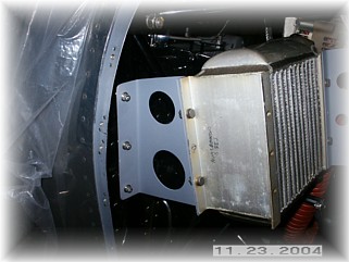
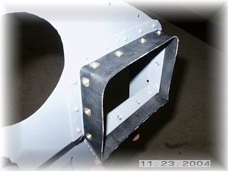
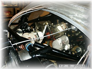
I decided to mount my cooler on the right side because it looks like there's more room over on this side. The plan is to mount the cooler to the engine mount and then route the air to the cooler using a two-part plenum. To mount the cooler, I fabricated two brackets out of .064 plate and attached them to the upright engine mount tubes using three cushion clamps on each one.
This seems to hold the cooler fairly rigidly. The bolts holding the cooler to the brackets are only temporary. They will be replaced with three bolts and spacers that go through both sides of the cooler. Also, I plan to slide the cooler up just a little higher than what's shown in this picture so that the lower oil cooler hose will duck under my hot air inlet SCAT tubing running to the cabin heat valve.
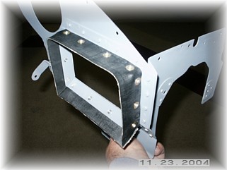
With the cooler mounted, I started on the plenum chamber. The first part of the chamber consists of a frame of .063 angle around the opening in the rear baffle with baffle seal riveted to that. The idea here is to minimize the weight added to the baffle since that's the part that vibrates and shakes.
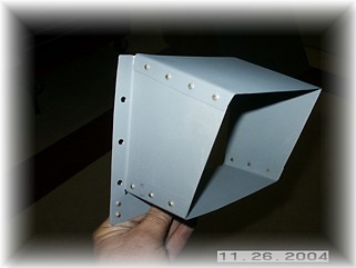
To match up to the cooler I made a plenum box. You'll notice that it doesn't match the total opening of the oil cooler. On Mark's advice, he suggested that the upper and lower floors of this box not diverge more than 11 degrees to reduce the chance of air turbulence in the plenum. I test fit every thing to make sure it all went together as planned.
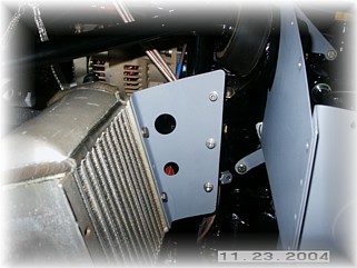
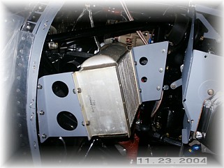
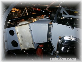
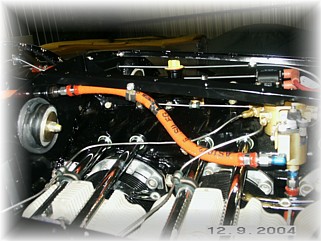
I then disassembled all the baffle parts and painted them with high temp engine enamel. Here's a shot of the oil cooler side of things, fully assembled.
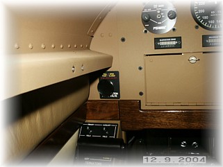
The purge valve is operated by a cable in the cockpit. It exits the firewall in the upper left side and proceeds straight into the rear of the baffles.
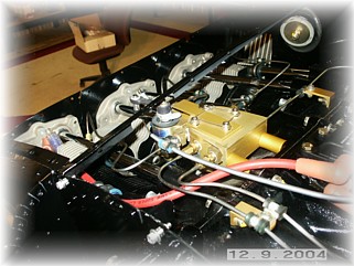
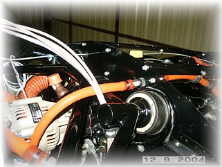
Here the cable is supported by the plenum support angles as it bends around to the purge valve handle. There, I used a "B" nut assembly from Aircraft Spruce to secure the cable to the arm. Missing in this picture is a spring that I installed that will hold the purge valve in the closed position should the cable become detached.
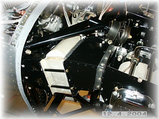
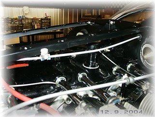
The fuel return lines run straight back to the rear baffle where a bulkhead fitting is used. The return line dives down behind the engine and into the firewall in the lower center quadrant. On the inside, the return line is plumbed to the input line of the right fuel tank prior to the fuel selector valve. Next step is to mount and wire up the ignition system. That work begins on the next page. |
||
|
"I must have an immense mind. It takes me as much as a week,
sometimes, to make it up." |