|
|
| Home-->F1 Rocket Project-->Engine Page 6 |
|
SITE CONTENTS
Please send your comments and suggestions to: Copyright
© 2008 by
|
Links
on this page: Engine Cowl |
|
|
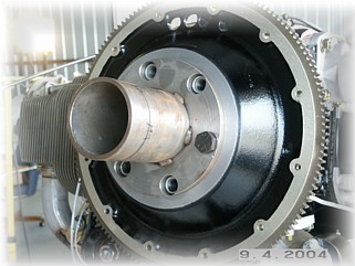
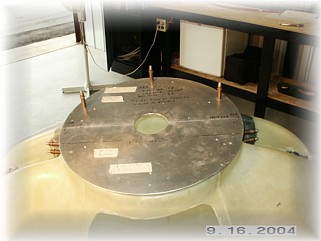
The first step to mounting the cowl is to mount the cowl alignment tool. This is a tool that Jim Winings made that all the Indy Gang is using. It has multiple grooves cut into the face to allow for the different prop and hub extensions.
According to the plans, I am supposed to trim the nose area to get the two cowling halves to go together. Yeah right. They don't fit at all. What you see here is about two hours of fiddling and trimming, and I'm still not happy with the fit. I've made some initial cuts along the length, but I've left the sides a tad long for the moment. Currently, I'm working to get the inlets somewhat symmetrical and the cowl ring circular. I've got a ways to go yet.
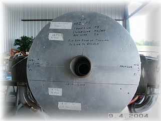
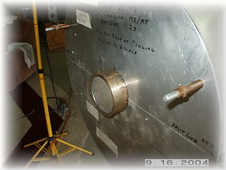
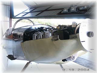
After another couple of days of hacking and pounding, I got the parts somewhat together. I then placed the mounting disk on the front and clecoed it to the cowl halves. This is where I decided to follow my own instructions for mounting the cowl. The thing I don't like about the instructions in the manual is that there's no real reference point you can use to get things set up straight and tight. I couldn't understand what measurement I was supposed to check in order to mount the hinges so I've decided to do things differently.
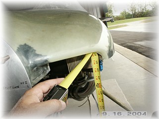
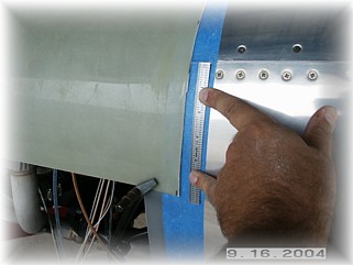
My first step is to mount the top hinge to the plate and sit it on the airframe. From this point, I leveled the airplane side-by-side and measured the cowl openings down to the floor. This levels the front of the cowl. When they were even, I put a couple of marks on the mounting ring as reference points.
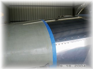
Next, I laid down a two inch strip of masking tape on the boot cowl to use as a reference point. I also checked to see if the lower edge of the top cowl was the same distance on both sides. The rear of the cowl will slide back and forth a little to make them even.
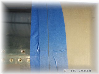
When I was sure that the upper cowl was level and positioned correctly fore and aft for my intended propeller, I laid down a second layer of tape, over the first one and on top of the cowl. I then laid down a third layer of tape on the cowl to mark my desired cut out line. This allows me to mark the cut line on the cowl so that I don't have to allow for the thickness of the cutting disk or thickness of the pencil mark. In short, it gives me the exact location of the cut line.
I removed all the tape except the last one and trimmed the cowl using my cut-off disk. The result is a perfect fit. Although I don't have a picture of it, I drilled the top cowl to the mounting flange using a 3 1/2 inch spacing. I found his spacing to be perfect in missing the corner of the engine mount and lining up with the top center of the cowl. I only drilled the holes #40 at this point. They will be drilled up to #30 after the fiberglass lay ups are applied because the fiberglass will screw up the hole alignment slightly. The mis-alignment can be corrected when the holes are drilled up in size. This positions the top cowl as the reference point for mounting the bottom cowl and for cutting the sides.
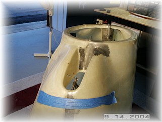
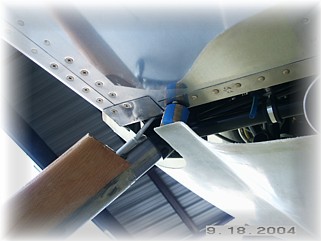
I removed the top cowl and mounted the bottom cowl to the cowling tool. I trimmed out around the gear legs to allow the bottom cowl to fit. Initially, I was having trouble getting the bottom cowl to fit until I noticed that the bottom cowl does not fit tight against the bottom skin. The pictures in the manual show an older version of the cowl. I found this out by looking at the upper gear leg fairings. I discovered that there is a 1 inch gap in the lower cowl. I made a spacer using some washers and clamped the lower cowl in place. I left the sides long at this point because the proper forward and aft location cannot be accurately determined until the cowls are hinged together.
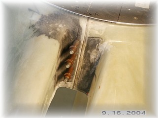
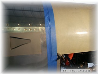
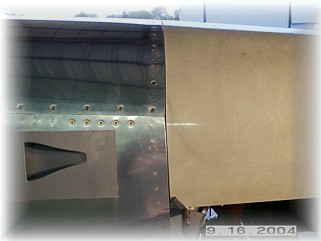
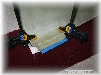
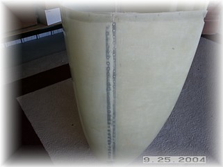
It was at this point that I discovered a major FUBAR. See the mark on the fuselage ABOVE the lower cowl? That's where my upper cowl stops. It seems that when my lower cowl was cut from the mold, the aft edge of the lower cowling was trimmed about two inches BELOW the trim line. After steaming about it for awhile, I went about fixing it. I clamped a piece of aluminum flush with the outside surface, and then applied a 5 ply filler, with only two of the plies attached to the inside of the cowl. I wanted to avoid a big buildup on the inside because the hinge will bulge.
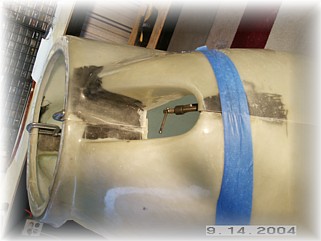
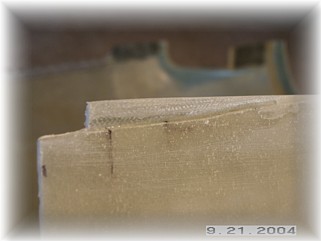
This is what the repair looked like after it was trimmed. With a little filler is should be okay, but I'm afraid that it might crack over time. With the FUBAR fixed, I clecoed the cowl halves together and drilled the hinges to both upper and lower cowl haves.
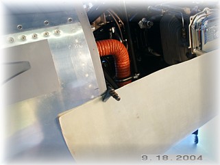
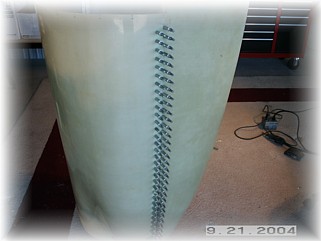
With the cowl halves attached together via the hinge, I put the cowls back on the airframe to get the final trimming measurements for the lower cowl. Using the same steps outlined for the upper cowl, I establish the final trim line. After removing the cowls and trimming the aft edge of the bottom cowl, I permanently attached the hinges to the cowls and applied a 4 ply lay-up around the aft edge of the cowls. Once it was dry, I re-mounted the cowl and drilled the attach holes up to #30 in size.
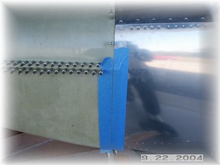
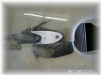
Up front, I fabricated a couple of polished clips to hold the hinge pin in place. This was the best I could come up with quickly. I may replace these after the airplane is painted. For now, they'll do the job just fine. Next, I'll get to work on the oil dipstick door. That work starts on the next page. |
||
|
"I do not regret the things I've done, but those I did not do." |