|
|
| Home-->F1 Rocket Project-->Elevators Page 1 |
|
SITE CONTENTS
Please send your comments and suggestions to: Copyright
© 2008 by
|
Links
on this page: Attach Stiffeners Assemble Skeletons |
|
|
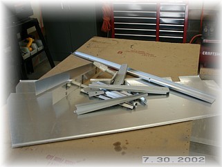
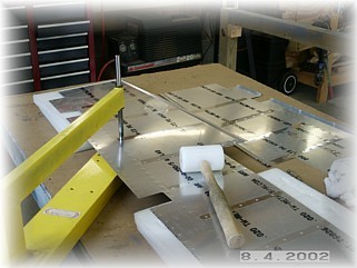
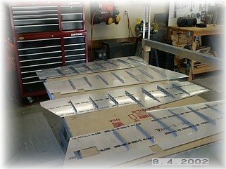
First step in assembling the elevators is to gather up all the parts and lay out the stiffeners.
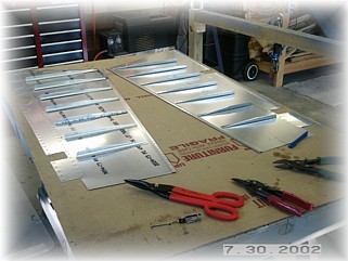
I set up a mini-assembly line to cut out, trim, and clean up all the stiffeners. This repetitive work is not that much fun but you have to do it to get to the goal at the end.
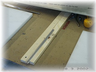
I laid the stiffeners between the wood strips, marked the centerline, and then laid the pre-punched skin over the it. Make sure you have the skin oriented properly before drilling any holes. (e.g.- top up the skin up and the bottom side down on the stiffener)
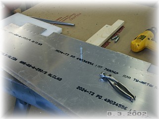
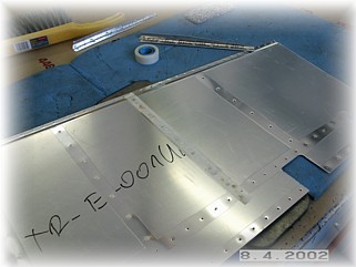
Once all the holes are drilled, I deburred and dimpled them. Go easy as these skins are pretty thin. It doesn't take much to dimple them or to put a crease in them.
Now it's time to set up the backing plate and rivet the stiffeners on. Very light gun pressure works best as it is easy to over set these rivets.
That completes the skins for now. I will place these aside and begin work on the skeletons.
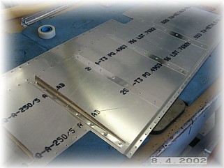
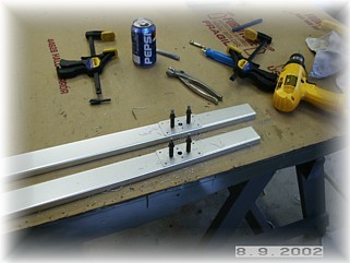
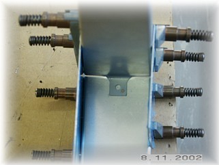
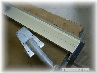
First step is to attach the reinforcing plates and the nut plates along the main elevator spar. These are laid out over the existing holes and drilled/riveted to the aft face of the elevator spar. Double check your nut plates before riveting them on. On my RV-7A project, I assembled the elevators only to find that one of the nut plates was a blank and didn't have any threads cut into it. That was not a fun discovery. I always check my nut plates now.
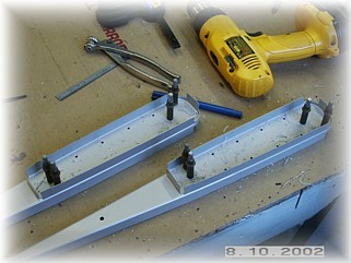
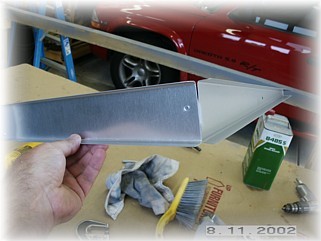
The tip ribs can be assembled now as well. These go together just like the rudder tip. The plans are a little vague in this area so you have to keep referring back to another section of the plans.
With both of these done, it is time to attach the tip rib to the spar. Again, this is done the same way as the rudder. Attaching the inside rib is a different matter. When you look at the rib, there is a tab on the forward web with a #12 hole in it. It is a tooling hole/tab used to form the rib. From what I can gather from the F1 Builders List, you are supposed to just cut this tab off and fit the rib to the rudder horn assembly after the rudder horn is mounted to the elevator spar. However, the problem I see with that approach is the difficulty in getting the horizontal plane of this rib correctly set with regard to the rudder horn and with regard to the spar, and most importantly, with regard to the other elevator. There are two alignments that are important to get right when building the elevators. One, you must get the elevator horns aligned with the centerline of the spar. If you don't, the horns will bind up with the center bearing when the elevators are deflected. Second, you want both horns to align with one another when both elevators are at the same deflection angle. If they aren't aligned properly, then the horns will not hit the elevator stops at the same time. So, I developed my own technique for getting all of this correct.
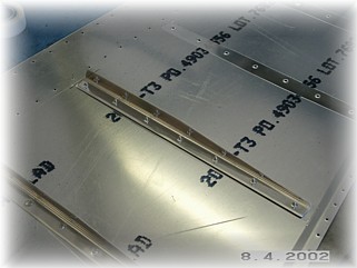
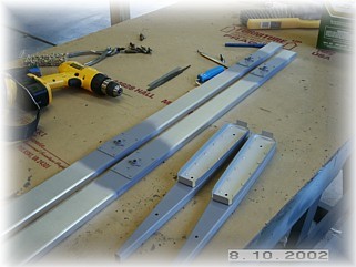
First, I bent the tab back and positioned it behind the spar, I placed the bend as close as I could to the web of the rib.
Then, I drilled a #40 hole in the tab. I dimpled and riveted the hole so that the rib is now attached to the spar. Now, all this does is free up my hands later on so I don't have to try and hold seven things together in perfect alignment in order to drill the attach holes.
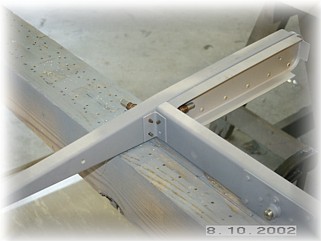
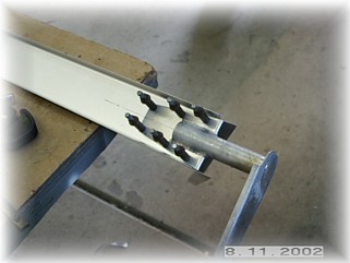
I drew centerlines on the face of the spar and on the rudder horn. The nice thing about these rudder horns is that at intersection of the two mounting "paddles", the horn is the same width as the spar web. This means that alignment to the spar is a snap. I just made sure that the alignment marks lined up and I drilled the horn to the spar. DO NOT drill the holes in the end rib just yet. Do this to both spars/rudder horns. If you sight down the spar through the hole in the rudder horn, you should see the eyes of the rod end bearings all in perfect alignment.
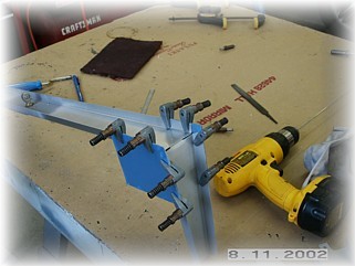
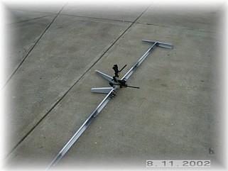
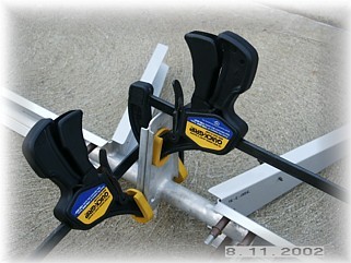
In order to get the two horns aligned with one another, I drilled ONE of the horns to the inside rib by centering it along the horizontal axis of the rib, much the same way I drilled it to the spar. This now becomes the basis for drilling the other horn. I then took the two spar assemblies out into my driveway and laid them flat. I clamped the horns together as shown. I then held the inside ribs down so that both of them were flat. While doing so, I drilled the attach holes through the other rudder horn and rib. Now I know that they will both be in the same plane (Ha ha, pun intended!) This completes the skeletons. Now it's time to build the jigs and attach the skins. |
||
|
|
||
|
"Our greatest battles are
that with our own minds." |