|
|
| Home-->F1 Rocket Project-->Wings Page 1 |
|
SITE CONTENTS
Please send your comments and suggestions to: Copyright
© 2002-2005 by
|
Links
on this page: Wing Prep Attach Aileron Flap Brace Electrical Conduit |
|
|
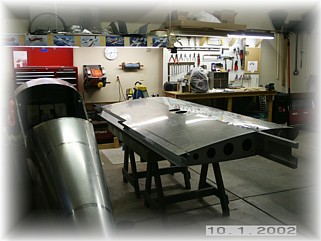
Work on the wings will coincide with work on the fuselage. These pictures will detail the right wing assembly and I will skip pictures of the left wing since it is the same thing over again. The only difference will be the pitot tube install in the left wing, which I will detail with pictures once I get there. The first order of business is to order the parts I will need in order to finish both wings. I sent in orders for my autopilot servos, strobe/position lights, wiring and electrical parts, and pitot. These will take a few days to get here so I will get started on hanging the control surfaces.
First step is to remove the bottom skin. This was easily done by drilling out the attach pop rivets. A thorough examination of the wing innards showed that those Czech builders are really, really good.
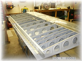
Next, I removed the three most inner ribs. These were easily removed by removing the nuts from the attach bolts. To reach the inner most bolts, I taped my box wrench to a long bladed screwdriver.
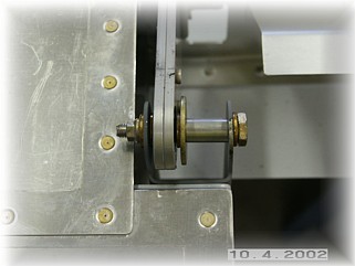
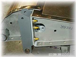
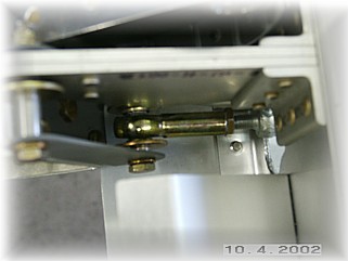
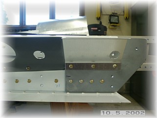
Attaching the aileron is a relatively simple process. I used the hardware provided in the kit to mount the aileron per the plans. These pictures show both the inboard and outboard attachments. You'll notice that I never use these fiber nuts on anything that I want to stay together, like control systems. I know this is just a phobia of mine but I trust the metal locking nuts much more than the fiber insert nuts. Also, I made spacers in place of the two washers used on the outboard attachment. I learned from my RV-6 that it's nearly impossible to fumble with these washers in a cold hangar, so I made the spacers to take their place. They are a little tough to make since they are so thin, but they are infinitely easier to install than the washers.
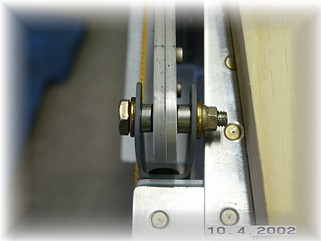
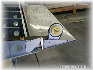
Here I am establishing the maximum deflection angle of the aileron. The plans call for extra washers underneath the lower bolt head on the outboard hinge, which acts as the stop. I used an angle gauge to determine the angle when the aileron is in trail at zero degree deflection. I then added the deflection angle to this and then set the bolt head accordingly. I added one regular washer and one thin washer to get the desired angle.
Since I had to take one of the bolts out, I took them all out and primed the hinge. I also replaced the fiber nuts with metal locking nuts and torqued them down. I did this to both hinges.
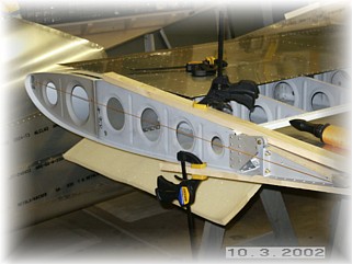
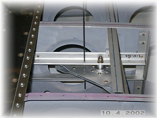
Next step is to establish the aileron in trail with the wing so that the bell crank hardware can be attached. I used a string to get the tooling holes in alignment and then clamped everything down to hold it there. I drilled the alignment holes in the bell crank and angle up to #40 size and used my long bit to hold the bell crank in position. With both the bell crank and aileron in the neutral position, I attached the control linkage.
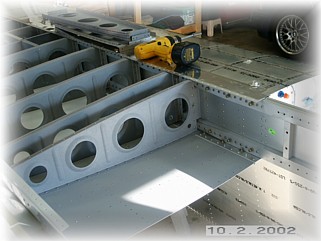
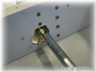
The control linkage was attached as outlined in the manual. Getting to the inside nut on the aileron is really hard. I ended up gluing a washer to a nut so that I could put them both on at the same time. Not very elegant but it worked. Here you can see how the opening was modified with a die grinder to allow for the proper travel of the control tube. It goes without saying, but I'll say it anyway. You don't want any binding whatsoever in your aileron controls. Everything must be very fluid so give yourself a little margin of error when trimming the hole larger.
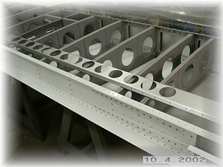
I removed the flap brace by drilling out the temporary pop rivets. The brace needs to be prepped before it is riveted on. First, the attach holes were drilled up to #30 and deburred. Second, I drilled access holes in both the long flap brace and the short one that is already riveted on. When the two most inboard wing ribs are riveted, I couldn't find a way to get to the second rivet from the bottom. So, I drilled holes large enough for my rivet set to fit through. The thing is drilled full of holes already so I figured two more small ones wouldn't make any difference.
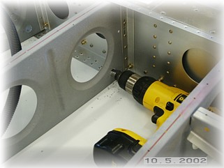
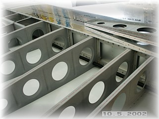
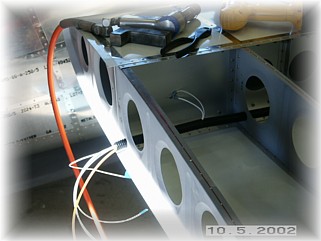
Now is the time to make all the allowances for electrical "stuff" in your wing. I ran a length of Van's plastic conduit down the length of the wing. First step is to drill the conduit holes up to 3/4". I then pulled the plastic through the holes starting in the middle of the wing and working my way out to either end. You have to figure out your wiring needs at this point. My RIGHT wing requires a 14 gauge wire for the landing light, a 16 gauge wire for the position lights; coax for the COMM antenna; and the strobe wire that comes with the Whelen installation kit. I will use the spar of the wing as a ground point.
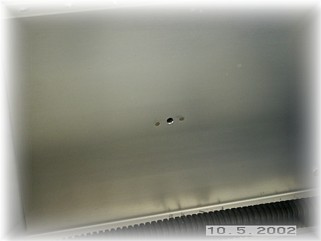
In the middle of the outboard rib, on the bottom, I installed a nut plate. This is where I will attach the ground wires for the landing light and position lights. Since the fiberglass tip is......well.....fiberglass, you have to run a ground wire for them to work. Although it doesn't show in this picture, I ground down the surface where the screw goes in to the nut plate to remove the anodizing. The wires outboard of the end rib will be terminated into Mate-N-Loc quick disconnects with gold-plated contacts. Since I am using the tip for the antenna and landing lights, I need be able to remove the wingtip. Next step is to finish the inboard ribs in preparation for riveting on the bottom skin. |
||
|
"Life
isn't about finding yourself. Life is about creating yourself." |